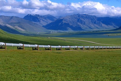
From oil pipes to Bag pipes, one thing is certain. Pipes are important for humanity!
A pipe is a tubular section or hollow cylinder, usually but not necessarily of circular cross-section, used mainly to convey substances which can flow — liquids and gases (fluids), slurries etc. It can also be used for structural applications.
The pipeline system that conveys the individual-well (oil well probably) production or that of a group of wells from a central facility to a central system or terminal location is a gathering pipeline. Generally, the gathering pipeline system is a series of pipelines that flow from the well production facilities in a producing field to a gathering “trunk” pipeline.
Gathering systems typically fall into one of four categories:
1. Single-trunk systems with “lateral” lines from each well production facility.
2. Loop systems, in which the main line is in the shape of a loop around the field.
3. The multiple-trunk system, in which there are several main lines extending from a central point.
4. Combinations of Categories 1 through 3.
In the pipeline industry it is necessary to verify that pipe used for gathering, transmission, and distribution lines can safely withstand operating pressures. Barlow’s formula relates the internal pressure that a pipe can withstand to its dimensions and the strength of its material. 
P is pressure (Pa) S the allowable stress (Pa), t the wall thickness (m) and D the outside diameter (m).
The equation, has other formulations too.
The design of a complex pressure containment system involves much more than the application of Barlow’s formula. For almost all pressure vessels, the American Society of Mechanical Engineers code stipulates the requirements for design and testing. The formula is also common in the pipeline industry to verify that pipe used for gathering, transmission, and distribution lines can safely withstand operating pressures. The design factor is multiplied by the resulting pressure which gives the maximum operating pressure (MAOP) for the pipeline. This design factor is dependent on class locations which are defined in United States Department of Transportation (DOT) Part 192. There are four class locations corresponding to four design factors:
Class 1: An offshore area or any class location unit that has 10 or fewer buildings intended for human occupancy. The Class 1 design factor is 0.72.
Class 2: any class location that has more than 10 but fewer than 46 buildings intended for human occupancy; design factor 0.60.
Class 3: any location that has more than 46 or more buildings intended for human occupancy or any area where the pipeline lies within 100 yards (91 meters) of a building or a small, well-defined outdoor area (such as a playground, recreation area, outdoor theater, or place of public assembly) that is occupied by 20 or more persons at least five days a week for 10 weeks in any 12-month period—weeks need not be consecutive. Design factor 0.50.
Class 4: any class location unit where buildings with four or more stories above the ground are prevalent; design factor 0.40.
Enough with pipes today. Now go and try using fxSolver, with the Barlow’s formula in our database.
Also, remember to follow our social media pages, by hitting the buttons below and watch the fxSolver video as well!
